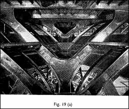
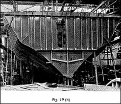
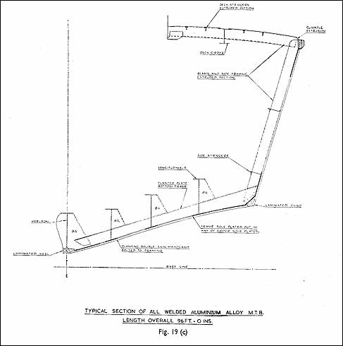
It was decided by the Director of Naval Construction that the basic load bearing structure should consist in welded aluminium, the bottom and sides would be of double diagonal mahogany planking. The planking is fastened to the aluminium by stainless steel bolts. (See Fig. 19 (a), (b) and (c).)
The air intake structure is formed from a fibre glass mould¬ing while a sheathing of this material is applied as a covering to the bottom up to boot topping level. The object here is to avoid soakage and the depredation of the teredo and other worms.
Structural calculations were carried out on instruction from the Director of Naval Construction making use of a method developed in this department (Ref. 6).
In addition consultation with N.C.R.E. (Naval Construction Research Establishment) was arranged on more than one occasion.
On the assumptions underlying the method of calculation depends the success of the result.
ELECTRICAL ARRANGEMENTS
In view of the great importance of reducing weight Vosper were asked by the Admiralty to make a thorough investigation of the whole of the proposed electrical installation with the object of redesigning the fittings where necessary.
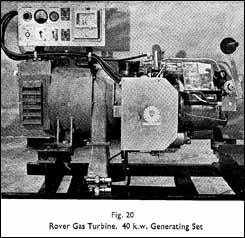
The first item for consideration was the generating plant, which, after consideration of a number of alternatives, eventually consisted of two units based on the Rover gas turbine combined with a generator developed by Metropolitan Vickers Ltd. These little units (Fig. 20) have given excellent service up to date. The only difficulty in service has arisen through the accidental ingestion of an oil spray from a neighbouring gearbox which caused instability.
As far as instrumentation was concerned, an instrument panel was developed making use of electrical instruments where edgewise lighting was arranged. This panel is not unlike those fitted in aircraft as, for instance, in the case of an engineer’s panel. This is shown in Fig. 14.
Though not altogether applicable strictly to electrical problems an interesting development consists in a “console” or light panel arrangement incorporating all the bridge controls and other instruments, and can be seen in Fig. 13. A particular feature here is that the console is subdivided into three portable and watertight sections, so arranged that almost immediate access is obtained to the back by detachment in a forward direction.
The many electrical fittings throughout the ship were carefully studied and many detailed improvements effected, which resulted in weight saving. In particular one of the most profitable moves consisted in the replanning of the many junction boxes making use of a light alloy fabricated construc¬tion in place of the usual castings and by the substitution of Hellerman’s neoprene tension grummets in place of gland bodies and units. A special light fitting was developed and considerable weight saving effected by the grouping of a number of navigational aids, an outstanding example being represented by the grouping of the Chernikeef Log units into one assembly. This alone saves 31 ¼ lb. weight.
The very far-sighted policy of the Director of Electrical Engineering in ordering Vosper to carry out this investigation must be acknowledged, as apart from the Fast Patrol Boat types all future warships will unquestionably require to make use of this type of fitting as the saving of weight has become important in all fields of transportation and, of course, in the navies of all countries. This tendency will continue.
TRIAL RESULTS AND CONCLUSIONS
The performance must be considered very satisfactory having regard to the fact that 51 knots has at times been exceeded over the measured mile at half fuel load and the appropriate armament load, which is the agreed trial con¬dition. During trials 50.25 knots was recorded, which speed would have been greater if it had not been such a hot day. Associated with this speed was a total s.h.p. of 9,000. Dis¬placement =85 tons.
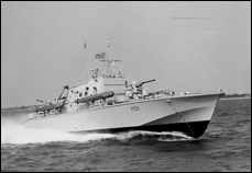
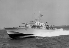
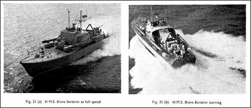
Manoeuvrability, which includes turning circles, is quite exceptional. This is largely due to the relatively powerful electro-hydraulic steering gear developed, which can be put over to 25° in 3 seconds. Whereas the “Staff requirement” called for a turning circle diameter not more than 8 lengths at full speed, the Brave Borderer achieved a turning circle diameter of 4 lengths at 50 knots. (See Fig. 21 (a) and (b).)
A long series of official Admiralty reversing and manoeuvring trials took place subsequent to the progressive trials, as follows:
Manoeuvring and Turning Trials
On 29th July 1959 the first of a series of manoeuvring and turning trials was carried out as specified by the Director of Marine Engineering of the Admiralty with the object of ascertaining the suitability of the reverse and reduction arrangements. At the same time torque measurements were recorded continuously on all three shafts, mainly with the idea of ascertaining the maximum transient torque accepted by the gearboxes under any particular conditions.
List of Trials
(1) All engines running ahead at revolutions for 10 knots.
Stop engines.
Astern on all engines until 5 knots way on astern.
This repeated five times making six in all.
(2) All engines running ahead at 15 knots.
Stop all engines.
Astern on all three till 5 knots way on astern.
Ahead on three engines (15 knots).
This repeated five times making six in all.
(3) Centre shaft in neutral.
Port engine ahead 3,000 power turbine revolutions.
Starboard engine astern 3,000 power turbine revolutions.
Turn through ‘180°.
Repeat with starboard engine in ahead and port astern.
‘180° turn.
Repeat this manoeuvre three times more making four in all.
(4) With all engines stopped engage ahead with all engines and increase to full power in 2 mins. by four equal increments of 2,000 r.p.m. at intervals of 24 secs, and one of 500 r.p.m. Then close throttles and engage neutral as rapidly as interlock gear will permit.
When boat speed is reduced to 10 knots engage astern and open throttles to 20% power until way on astern, then stop.
(5) Exactly as for above but reaching full power in 1½ mins. When speed is reduced to 12½ knots engage astern and open throttles to 20% power.
(6) As above but increasing to full power in one minute then reducing speed and engaging astern to 20% till way is off.
(7) As above but increasing to full power in 30 sees.
Close throttles and engage neutral. When speed is reduced to 15 knots engage astern open to 3,000 p.t.r.p.m. until astern way on then stop. Note that only 15 sees, was required from 50 knots ahead to engines running astern! Turning trials were carried out at full speed applying helm angles up to 25° either way resulting in a turning circle diameter of 4.5 boat lengths. This was associated with maximum yawing velocity of 25°/sec.
At a later date a similar trial was ordered of approximately the same severity and duration.
An addition to the programme consisted in running up all engines to full power then applying 20° helm as quickly as possible, first to port then when in steady turn to starboard.
As far as could be ascertained from the running record of torque the maximum transient reading was 130% of the full torque recorded in ahead steady running.
Worthy of special mention is the fact that, from engines idling - gears in neutral, ahead was engaged and a speed of 50 knots was achieved in 30 sees. The throttles were then closed as quickly as possible and astern was engaged as soon as the safety interlocking gear would allow of this.
From 50 knots ahead, the shafts were revolving astern in 15 secs. and in a total of 35 secs, elapsed time the ship had on 5 knots sternway. This procedure was repeated a number of times.
In this trial alone gearbox reversals of torque were accom¬plished 36 times.